Time Delay Relay Circuit Using 555 Timer Ic Off Delay T

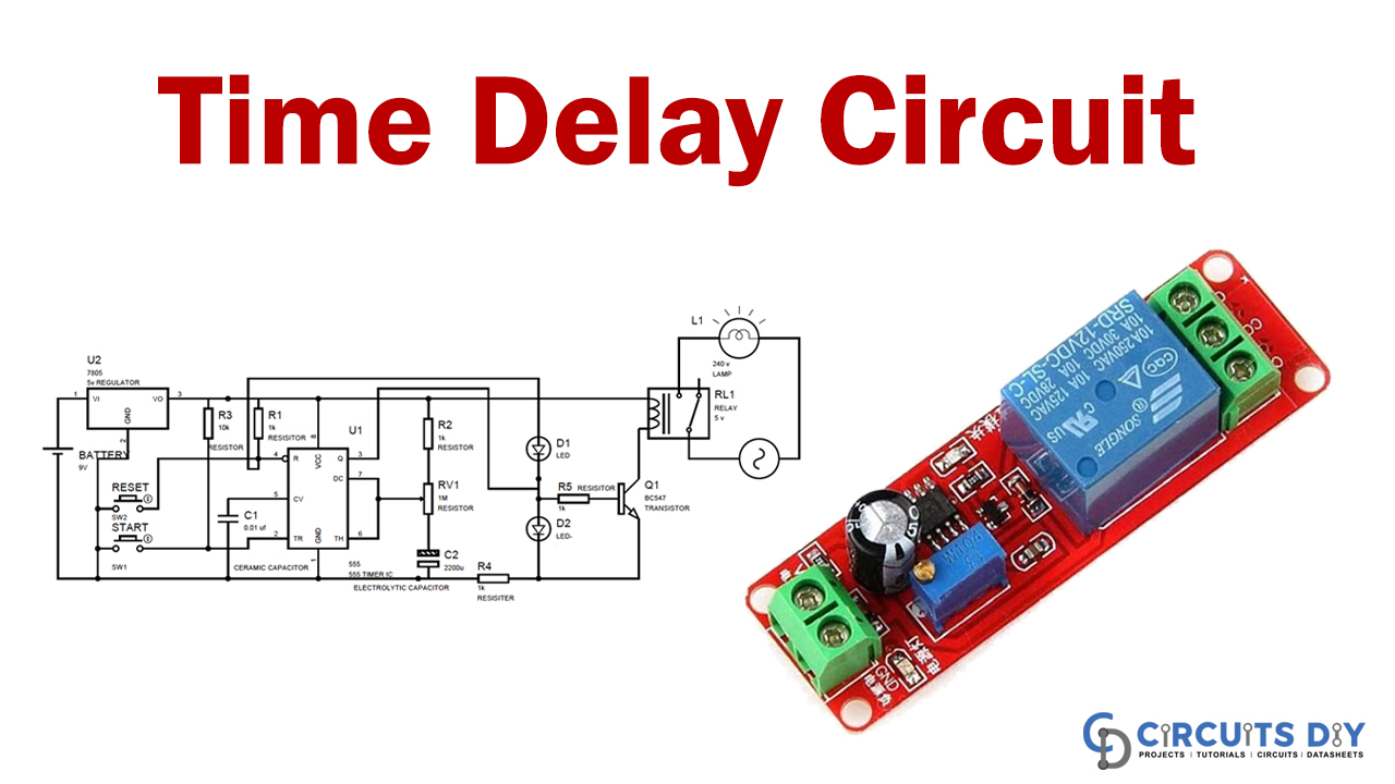
Time Delay Relay Circuit Using 555 Timer Ic Offођ In this 555 timer project, i have shown how to make a time delay relay circuit using 555 timer ic to automatically turn off the switch after a predefined delay. you can also adjust the off delay time up to 20 minutes with a 1m pot. in this article, i have shared the required components, complete circuit diagram, pcb layout, and all other. In this 555 timer project, i have shown how to make a time delay relay circuit using 555 timer ic to automatically turn off the switch after a predefined del.

Time Delay Relay Using 555 Timer Ic 4 application. in this tutorial, we will show you how to make a time delay circuit using 555 timer ic. the main principle of this circuit is to generate a pulse signal after some time delay. a time delay circuit can be useful for any circuit that needs a delay before the output turns on. in order to obtain time delay, we are using a 555 timer. Creating a time delay relay circuit with the 555 timer ic:in this 555 timer project, i have shown how to make a time delay relay circuit using 555 timer ic t. Step 1: 555 timer ic in monostable mode. lets start by putting all the components together and lets understand how the circuit works. in the first example, i am going to show you guys the "on off timer circuit" with a fixed timing resistor and capacitor. the heart of this circuit is the 555 timer ic. In this tutorial, we are going to show you how to make a time delay relay circuit using a 555 timer ic. this circuit is able to trigger the relay from a few seconds to a few minutes after pushing the switch s1. it is easy to make and uses only a few components. a relay is a switch that is operated electrically between two terminals that are.

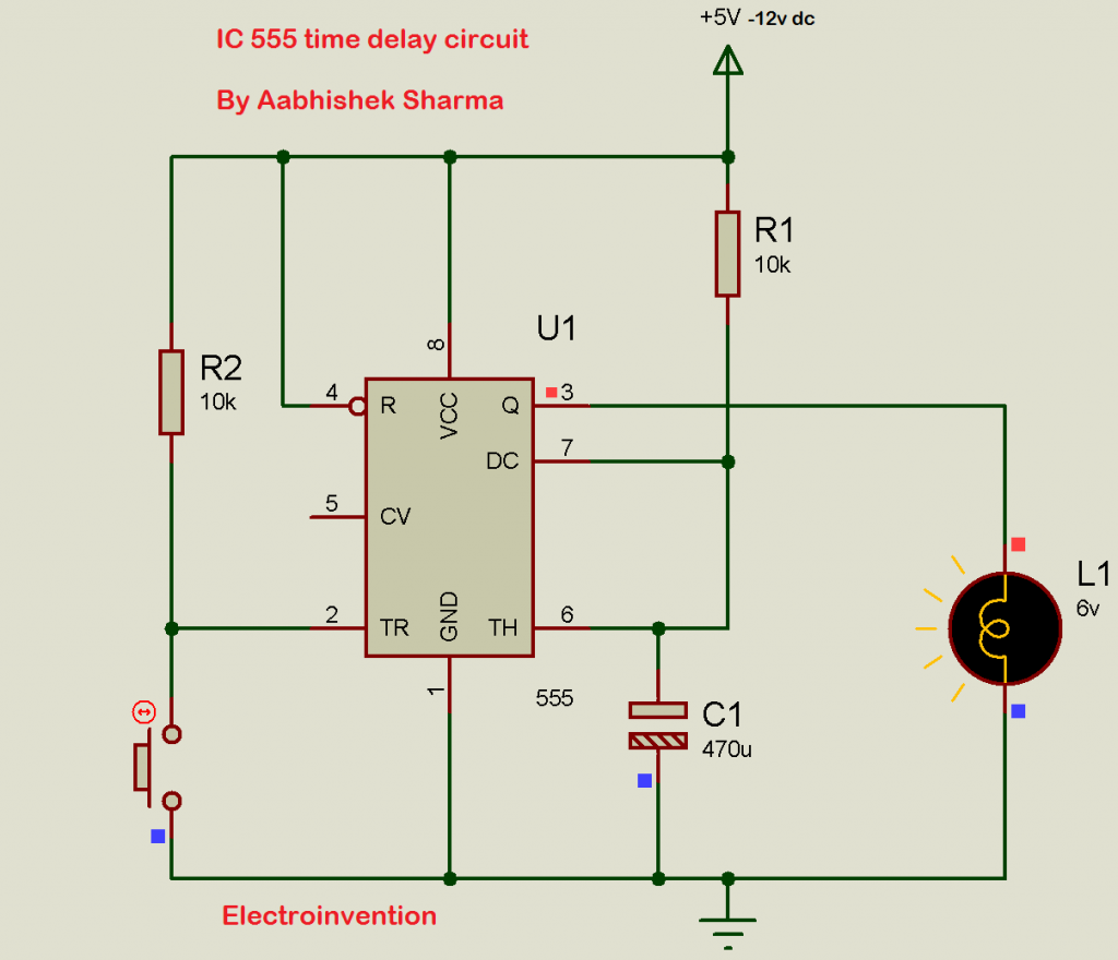
Time Delay Circuit With Relay Step 1: 555 timer ic in monostable mode. lets start by putting all the components together and lets understand how the circuit works. in the first example, i am going to show you guys the "on off timer circuit" with a fixed timing resistor and capacitor. the heart of this circuit is the 555 timer ic. In this tutorial, we are going to show you how to make a time delay relay circuit using a 555 timer ic. this circuit is able to trigger the relay from a few seconds to a few minutes after pushing the switch s1. it is easy to make and uses only a few components. a relay is a switch that is operated electrically between two terminals that are. If the trigger pin (pin 2 of the 555 timer ic) senses any voltage less than 1 3rds of the supply voltage, it turns on the output. if the threshold pin (pin 6 of the 555 timer ic) senses any voltage more than 2 3rds of the supply voltage, it turns off the output. whenever the output of the 555 timer ic is in off state, the discharge pin (pin 7. Before going into detail of time delay circuit, first we need to learn about 555 timer ic first. below you can find the pin diagram of 555 timer ic along with the details of each pin. pin 1. ground: this pin should be connected to ground. pin 2. trigger: trigger pin is dragged from the negative input of comparator two.

Ic 555 Delay Timer Circuit On Off Delay Circuit Elec If the trigger pin (pin 2 of the 555 timer ic) senses any voltage less than 1 3rds of the supply voltage, it turns on the output. if the threshold pin (pin 6 of the 555 timer ic) senses any voltage more than 2 3rds of the supply voltage, it turns off the output. whenever the output of the 555 timer ic is in off state, the discharge pin (pin 7. Before going into detail of time delay circuit, first we need to learn about 555 timer ic first. below you can find the pin diagram of 555 timer ic along with the details of each pin. pin 1. ground: this pin should be connected to ground. pin 2. trigger: trigger pin is dragged from the negative input of comparator two.

Comments are closed.