Tutorial 5 Pin Cdi Wiring Diagram

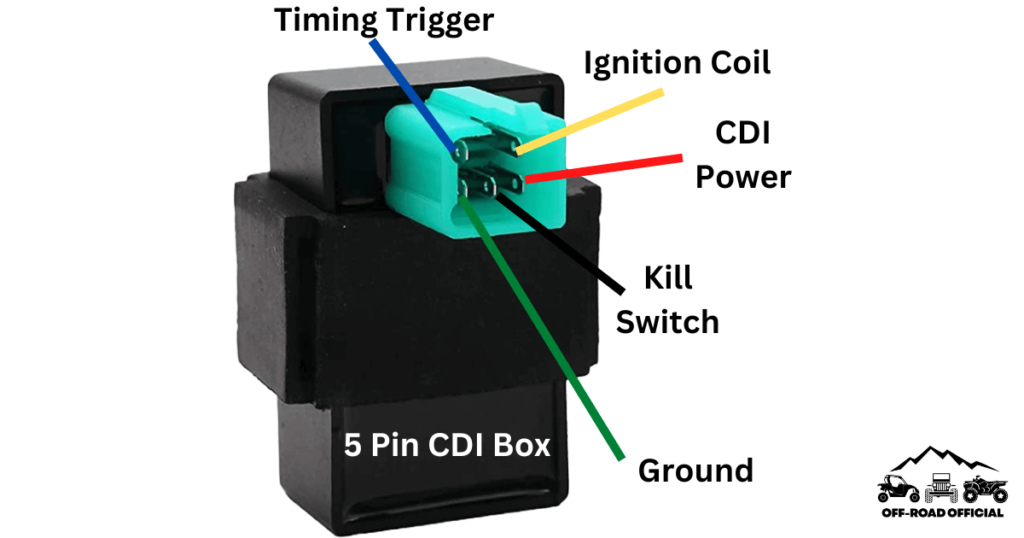
5 Pin Cdi Wiring Diagram Pictured And Explained Off Road Official The 5 pin cdi box. the 5 pin cdi comes in the form of a black box, fitted with a male connector at the top. inside of this male connector, there are five different pins that connect to the various parts of the ignition system to provide power to the machine. these five pins connect the timing trigger pulse generator, ignition coil, ignition. On a 5 pin cdi system, you will find 5 different colored wires coming out of the cdi unit: green – connects to pickup coil signal input. white – connects to ac input from stator. red – main power source ( 12v from battery) black – main ground ( connection to battery) blue – output to ignition coil.

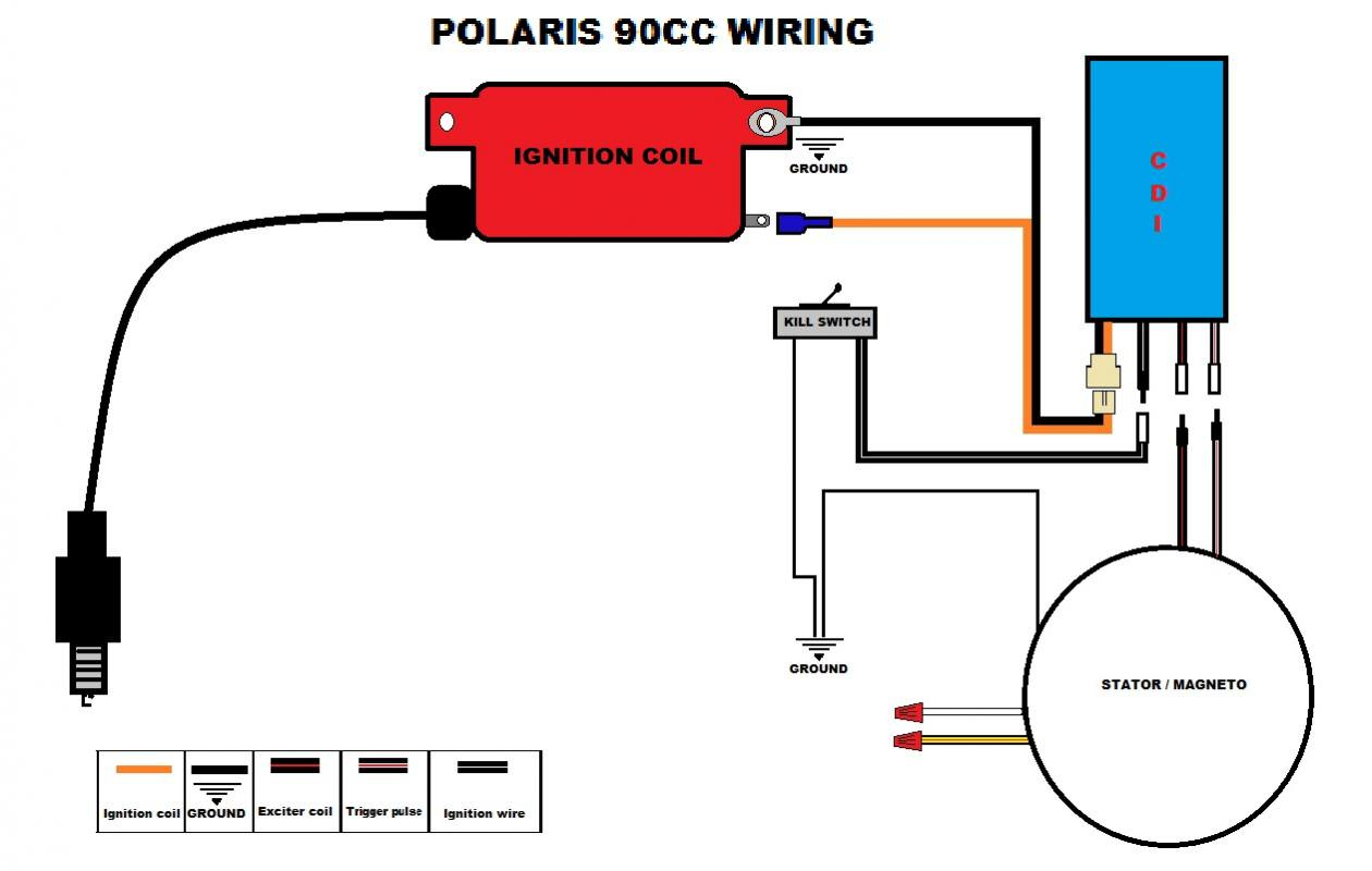
5 Pin Cdi Wiring Diagram Pictured And Explained Off Road Official Wiring a cdi involves connecting various wires and components, such as the stator, pickup coil, and ignition coil, in the correct sequence and configuration. this diagram shows you exactly how to wire a 5 pin cdi. each wire is labeled and color coded, making it easy to identify and connect the correct wires. Try edrawmax and make 5 pin cdi wiring diagram easily bit.ly 3bjwffz explore wiring diagrams, and free use and edit 5000 diagram examples here http. A 5 pin cdi box wiring diagram is a schematic representation of the electrical connections and circuitry inside a 5 pin cdi (capacitor discharge ignition) box. cdi boxes are electronic devices used in small engines, such as motorcycles, atvs, and dirt bikes, to ignite the spark plugs and control the timing of the engine’s ignition system. A 5 pin cdi works by using a capacitor to store energy and then releasing it in a controlled manner to fire the spark plugs. the following is a simplified overview of how a 5 pin cdi works: 1. the battery positive wire provides power to the cdi. 2. the battery negative wire grounds the cdi. 3. the ignition coil primary wire provides power to.

How To Draw 5 Pin Cdi Wiring Diagram Edrawmax Tutorial Youtube A 5 pin cdi box wiring diagram is a schematic representation of the electrical connections and circuitry inside a 5 pin cdi (capacitor discharge ignition) box. cdi boxes are electronic devices used in small engines, such as motorcycles, atvs, and dirt bikes, to ignite the spark plugs and control the timing of the engine’s ignition system. A 5 pin cdi works by using a capacitor to store energy and then releasing it in a controlled manner to fire the spark plugs. the following is a simplified overview of how a 5 pin cdi works: 1. the battery positive wire provides power to the cdi. 2. the battery negative wire grounds the cdi. 3. the ignition coil primary wire provides power to. The 5 pin cdi wiring diagram is a crucial tool for automotive repair professionals. it provides vital information about the internal workings of a car’s electronic ignition system. this diagram is typically used to troubleshoot issues with a vehicle’s engine performance, such as a shorted spark plug wire. with a 5 pin cdi wiring diagram. The 5 pin cdi diagram: a simple guide to understanding its functionthe world of motorcycles can seem complex and intimidating, especially for beginners. with so many different parts and components, it can be overwhelming to try and understand how each one works. one crucial part of a motorcycle's ignition system is the 5 pin cdi (capacitor discharge ignition)… read more ».

5 Pin Cdi Box Wiring Diagram For Your Needs The 5 pin cdi wiring diagram is a crucial tool for automotive repair professionals. it provides vital information about the internal workings of a car’s electronic ignition system. this diagram is typically used to troubleshoot issues with a vehicle’s engine performance, such as a shorted spark plug wire. with a 5 pin cdi wiring diagram. The 5 pin cdi diagram: a simple guide to understanding its functionthe world of motorcycles can seem complex and intimidating, especially for beginners. with so many different parts and components, it can be overwhelming to try and understand how each one works. one crucial part of a motorcycle's ignition system is the 5 pin cdi (capacitor discharge ignition)… read more ».

5 Pin Cdi Wiring Diagram Color Code

Comments are closed.