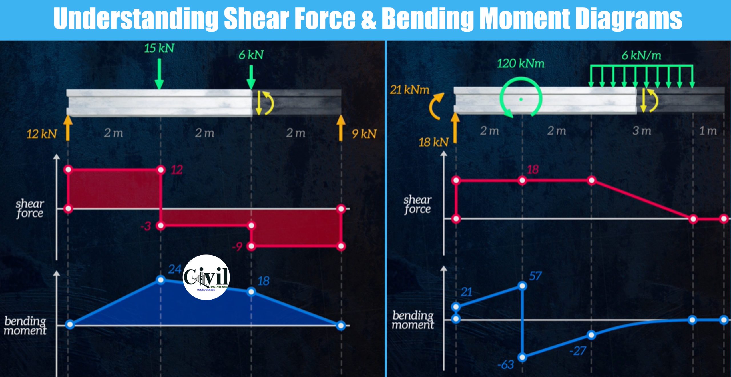
Understanding Shear Force And Bending Moment Diagrams

Understanding Shear Force And Bending Moment Diagrams Engineering Understanding shear force and bending moment diagrams. 4.1: shear and bending moment diagrams.

Understanding Shear Force And Bending Moment Diagrams Youtube Ultimate guide to shear force and bending moment. The ultimate guide to shear and moment diagrams. Therefore the bending moment diagram is: example 2 draw the shear force and bending moment diagrams for the beam show below: a) determine the reactions at the supports taking moments about a (clockwise moments = anti clockwise moments) (10 x 6) x 3 = 6rc where 10 x 6 =60kn = total load and 3m =distance from a to where the load is acting. 6rc=180. Our today's video is about understanding shear force and bending moment diagrams! in this detailed tutorial, we'll explore the powerful graphical methods use.

Learn How To Draw Shear Force And Bending Moment Diagrams Engineering Therefore the bending moment diagram is: example 2 draw the shear force and bending moment diagrams for the beam show below: a) determine the reactions at the supports taking moments about a (clockwise moments = anti clockwise moments) (10 x 6) x 3 = 6rc where 10 x 6 =60kn = total load and 3m =distance from a to where the load is acting. 6rc=180. Our today's video is about understanding shear force and bending moment diagrams! in this detailed tutorial, we'll explore the powerful graphical methods use. It is critical that all structural engineers understand how to draw bending moment and shear force diagrams. most structural designs relay on knowing the cor. Shear and moment diagrams are graphs which show the internal shear and bending moment plotted along the length of the beam. they allow us to see where the maximum loads occur so that we can optimize the design to prevent failures and reduce the overall weight and cost of the structure. since beams primarily support vertical loads the axial.

Comments are closed.