What Is 555 Timer Ic 555 Timer Working Internal Circuit Of 555 Timer

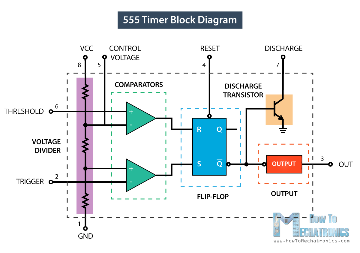
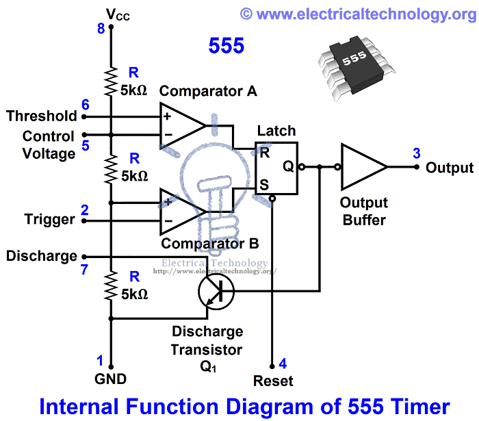
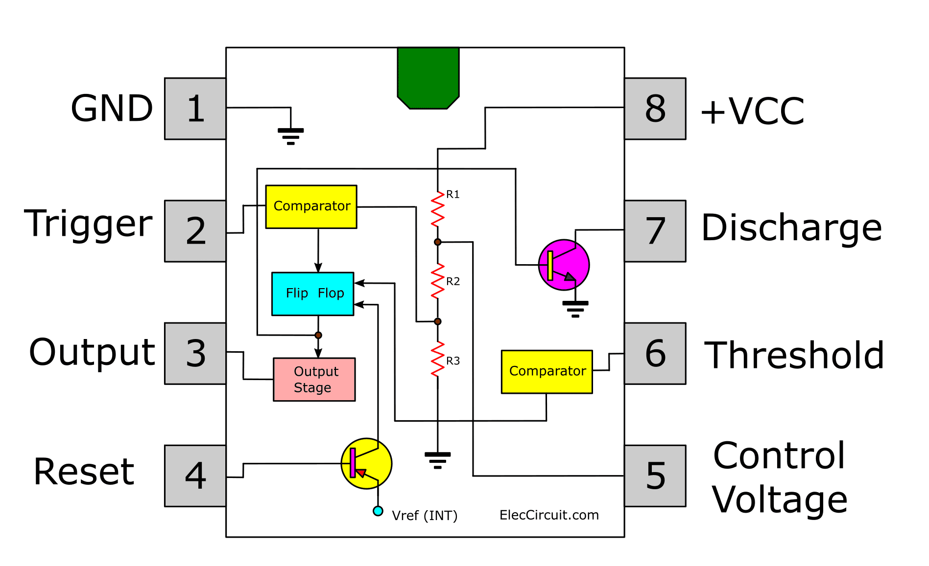
555 Timer Tutorial How It Works And Useful Example Circuits Here’s the internal schematics of 555 timer which consists of 25 transistors, 2 diodes and 15 resistors. represented with a block diagram it consists of 2 comparators, a flip flop, a voltage divider, a discharge transistor and an output stage. the voltage divider consists of three identical 5k resistors which create two reference voltages at. A 555 timer can give out only 100 to 200 ma in total. check your chip’s datasheet for the exact value. this pin resets the whole circuit. it’s an “inverted” pin, which means it resets when the pin goes low. this means the pin must be high normally so that the chip isn’t in a “reset” state.

Ic 555 Timer Internal Circuit Diagram 555 timer is a digital monolithic integrated circuit (ic) which may be used as a clock generator. in other words, 555 timer is a circuit which may be connected as a stable or monostable multivibrator. in more simple words, 555 timer is a monolithic timing circuit, which can produce accurate timing pulses with 50% or 100% duty cycle. The 555 timer ic is a very cheap, popular and useful precision timing device which can act as either a simple timer to generate single pulses or long time delays, or as a relaxation oscillator producing a string of stabilised waveforms of varying duty cycles from 50 to 100%. the 555 timer chip is extremely robust and stable 8 pin device that. The 555 timer ic is an integrated circuit used in a variety of timer, delay, pulse generation, and oscillator applications. it is one of the most popular timing ics due to its flexibility and price. derivatives provide two (556) or four (558) timing circuits in one package. [2]. The se 555 timer ic works between the temperature range of – 55°c to 125°c in se and the ic ne 555 is used for where the temperature ranges from 0° to 70°c. it has a wide range of usages in the electronic field as a timer, delay, pulse generation, oscillator, etc. you can check the datasheet of ne555 ic if you want to learn more about it.

555 Timer Construction Operation Electrical Technology The 555 timer ic is an integrated circuit used in a variety of timer, delay, pulse generation, and oscillator applications. it is one of the most popular timing ics due to its flexibility and price. derivatives provide two (556) or four (558) timing circuits in one package. [2]. The se 555 timer ic works between the temperature range of – 55°c to 125°c in se and the ic ne 555 is used for where the temperature ranges from 0° to 70°c. it has a wide range of usages in the electronic field as a timer, delay, pulse generation, oscillator, etc. you can check the datasheet of ne555 ic if you want to learn more about it. Important characterstics of 555 timer ic. ne555 ic is a 8 pin device. the important electrical characteristics of timer are that it should not be operated above 15v, it means the source voltage cannot be higher than 15v. second, we cannot draw more than 100ma from the chip. Learn the basics of how a 555 timer ic works in this educational video. watch the circuit diagram, the components, and the output waveforms.

Timer 555 Circuit Diagram Important characterstics of 555 timer ic. ne555 ic is a 8 pin device. the important electrical characteristics of timer are that it should not be operated above 15v, it means the source voltage cannot be higher than 15v. second, we cannot draw more than 100ma from the chip. Learn the basics of how a 555 timer ic works in this educational video. watch the circuit diagram, the components, and the output waveforms.

Comments are closed.