What Is P And Id Diagram Excel

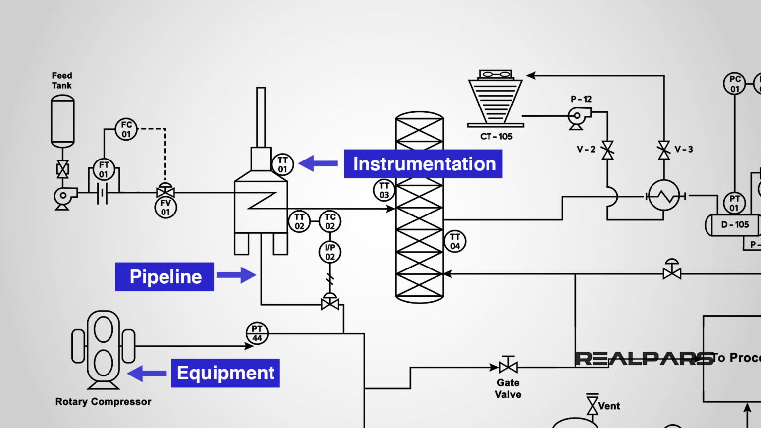
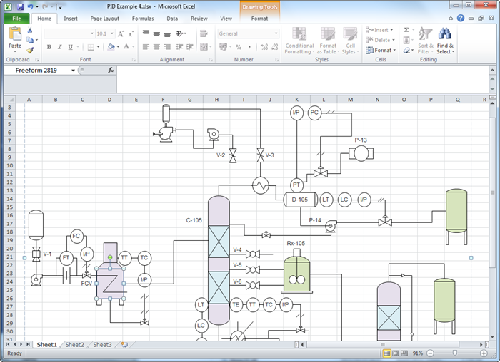
What Is P And Id Diagram Excel On the data tab, click shape data window. right click on shape data window and select shape data sets. click add, and then type a name for the shape data set. choose whether to create a new shape data set, a set based on the currently selected shape, or a set based on an existing shape data set, and then click ok. Excel 57. 0. abbreviated as p&id, a piping and instrumentation diagram is an articulate drawing of a processing plan that entails the piping and process equipment with its instrumentation and control machinery. it displays the piping and associated parts of a physical process flow. such diagrams are famous in the engineering field.

Create P Id For Excel Our program helps you get started with a p&id quickly, and export to excel format instantly with one button click. edraw is purposely designed with full integration with ms office so exporting edraw into excel requires only 1 click. after finishing a p&id, switch to file tab, click export button and choose excel to save your file as xlsx format. Function and purpose of p&ids. p&ids are foundational to the maintenance and modification of the process that it graphically represents. at the design stage, the diagram also provides the basis for the development of system control schemes, like hazard and operability study (hazop). for processing facilities, it’s a graphic representation of. A piping and instrumentation diagram (p&id) is a detailed engineering diagram indicating and depicting the relationship between piping, process equipment, instrumentation, and control devices. a p&id is used to describe the overall engineering processes. it shows the i nterconnection of process equipment and instrumentation to control the. A piping and instrumentation diagram drawing (p&id) is defined by the institute of instrumentation and control as follows: a diagram which shows the interconnection of process equipment and the instrumentation used to control the process. in the process industry, a standard set of symbols is used to prepare drawings of processes.

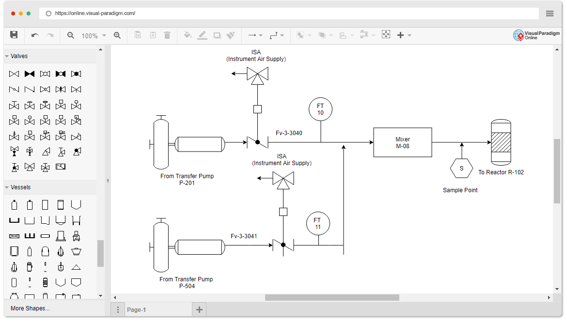
Create P Id For Excel A piping and instrumentation diagram (p&id) is a detailed engineering diagram indicating and depicting the relationship between piping, process equipment, instrumentation, and control devices. a p&id is used to describe the overall engineering processes. it shows the i nterconnection of process equipment and instrumentation to control the. A piping and instrumentation diagram drawing (p&id) is defined by the institute of instrumentation and control as follows: a diagram which shows the interconnection of process equipment and the instrumentation used to control the process. in the process industry, a standard set of symbols is used to prepare drawings of processes. A p&id drawing serves as a guide for start up and operational data. it is the basic training document to explain the process details to operation guys, field engineers, and maintenance professionals. the p&id drawings help them to track the interconnection between the piping and instrumentation and equipment. Reading p&ids is crucial for understanding the process flow in industrial plants. start by identifying major equipment such as pumps, tanks, and vessels. follow the flow of piping, noting valves, instruments, and fittings. p&ids use symbols to represent components, with arrows indicating the flow direction.

Piping And Instrumentation Diagram P Id Software A p&id drawing serves as a guide for start up and operational data. it is the basic training document to explain the process details to operation guys, field engineers, and maintenance professionals. the p&id drawings help them to track the interconnection between the piping and instrumentation and equipment. Reading p&ids is crucial for understanding the process flow in industrial plants. start by identifying major equipment such as pumps, tanks, and vessels. follow the flow of piping, noting valves, instruments, and fittings. p&ids use symbols to represent components, with arrows indicating the flow direction.

Comments are closed.