Wiring A 3 Phase Motor With Thermostat Leads

Wiring A 3 Phase Motor With Thermostat Leads Ok, so ideally, what you need to do is wire p1 and p2 into your control circuit so that if it becomes 'open' by the action of the thermostat inside the motor, it will shut down the motor. The electric motor wiring diagram below illustrates internal motor protection by a thermal switch like the thermostat: thermistors or positive temperature coefficient sensors (ptc) thermistors are built into the motor windings and protect the motor against locked rotor conditions, continuous overload and high ambient temperature.

Wiring A 3 Phase Motor With Thermostat Leads In single phase motors one single thermal switch is used. in three phase motors 2 thermal switches connected in series are placed between the phases of the motor. in that way all three phases are in contact with a thermal switch. thermal switches can be retrofitted on the coil end, but the result is an increased reaction time. Jul 11, 2012. #3. the "j" leads are usually internal thermostat leads used to shut down the motor on high winding temperature. i am not sure about the "manual momentary start" comment. i think they are looking for a motor starter with a three wire start stop circuit. the "j" leads would be connected to the control circuit to drop the starter. W2 cj2 ui vi wi w2 cj2 ui vi wi a cow voltage y high voltage z t4 til t12 10 til t4 t5 ali l2 t12 ti blu t2 wht t3.org t4 yel t5 blk t6 gry t7 pnk. P1 and p2 are likely thermostat leads, not sure if for controlling the heater or if for thermal overload protection of the motor though. h1 thru 4 is probably heater leads, connect them in series for the high voltage rating and in parallel for the low voltage rating. there should be information on them on the motor nameplate.

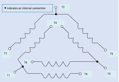
Wiring A 3 Phase Motor With Thermostat Leads W2 cj2 ui vi wi w2 cj2 ui vi wi a cow voltage y high voltage z t4 til t12 10 til t4 t5 ali l2 t12 ti blu t2 wht t3.org t4 yel t5 blk t6 gry t7 pnk. P1 and p2 are likely thermostat leads, not sure if for controlling the heater or if for thermal overload protection of the motor though. h1 thru 4 is probably heater leads, connect them in series for the high voltage rating and in parallel for the low voltage rating. there should be information on them on the motor nameplate. The most common type of three phase motor is that which has nine labeled (and often colored) wires coming out of the box on the side. there are many motors with more or fewer wires, but nine is the most common. these nine wire motors may be internally connected with either a wye (star) or a delta configuration, established by the manufacturer. 23 motor lead connections. 23. motor lead connections. three phase motors use coils of wire to create magnetic fields and produce rotation. standard 3 phase motors use six individual coils, two for each phase. the internal construction and connection of these coils inside of the motor is predetermined when the motor is manufactured.

Comments are closed.